
Investment casting tolerances
Linear dimensions, angles, geometry, wall thicknesses, radii and surfaces according to BDG/VDG P 690, the technical reference adopted by SR Tech.
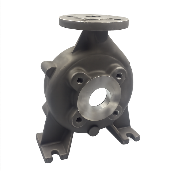
BDG/VDG P 690 as the reference for investment casting
SR Tech uses BDG/VDG P 690 as its technical reference when assessing tolerances for components manufactured by the lost-wax investment casting process. This German guideline is specific to the process and considers the combined effects of alloy, dimensions, geometry, pattern, ceramic shell and production cycle.
For stainless steels, carbon and alloy steels and, more generally, iron-, nickel-, cobalt- and copper-based alloys, material group D applies. P 690 defines three accuracy grades and covers not only linear dimensions, but also angular tolerances, radii, wall thicknesses, surface roughness, machining allowances and design guidance.
Form, orientation and location tolerances are not derived from a universal numerical table: they require datums defined on the drawing, specification in accordance with DIN EN ISO 1101 and a specific agreement between customer and supplier. This distinction prevents a linear tolerance from being incorrectly extended to the overall geometry of the casting.
ISO 8062-3:2023 is also included on this page as an international comparison for metal castings. Unless the drawing or specification requires a different reference, SR Tech begins its technical assessment from P 690 and confirms feasibility on the actual component before tooling is manufactured.
BDG/VDG P 690
SR Tech's operational reference for linear and angular tolerances, form and location, radii, walls, surfaces and machining allowances.
SR Tech referenceSerie ISO 8062
General international reference for metal castings, included for comparison and applied when required by the drawing.
International comparisonLinear dimensions according to BDG/VDG P 690
Material group D applies to the alloys normally supplied by SR Tech. Values shown as ± are half of the total DCT zone, assumed to be symmetrical about the nominal dimension.
VDG P 690 - Material group D
Values in millimetres, expressed as a symmetrical ± deviation from the nominal dimension.
| Nominal dimension | D1 | D2 | D3 |
|---|---|---|---|
| Up to 6 | ±0.15 | ±0.12 | ±0.10 |
| Over 6 up to 10 | ±0.18 | ±0.14 | ±0.11 |
| Over 10 up to 18 | ±0.22 | ±0.17 | ±0.14 |
| Over 18 up to 30 | ±0.26 | ±0.20 | ±0.17 |
| Over 30 up to 50 | ±0.40 | ±0.31 | ±0.25 |
| Over 50 up to 80 | ±0.45 | ±0.37 | ±0.30 |
| Over 80 up to 120 | ±0.55 | ±0.44 | ±0.35 |
| Over 120 up to 180 | ±0.80 | ±0.65 | ±0.50 |
| Over 180 up to 250 | ±1.20 | ±0.95 | ±0.75 |
| Over 250 up to 315 | ±1.30 | ±1.10 | ±0.80 |
| Over 315 up to 400 | ±1.80 | ±1.40 | — |
| Over 400 up to 500 | ±2.00 | ±1.60 | — |
| Over 500 up to 630 | ±2.70 | ±2.20 | — |
| Over 630 up to 800 | ±3.10 | ±2.50 | — |
| Over 800 up to 1,000 | ±3.60 | — | — |
VDG note: P 690 specifies the total DCT zone. Its position relative to the nominal dimension may be freely defined; this page uses the recommended symmetrical arrangement, so the ± values correspond to DCT/2. Any different arrangement must be stated on the drawing.
Complete P 690 requirements
Guidance applicable to investment cast components. The following tables refer to material group D wherever the material affects the value.
Form, orientation and location
These tolerances cannot be replaced by a linear D1, D2 or D3 value alone.
P 690 covers geometrical tolerances used to limit deviations in form, orientation and location, but does not provide one general numerical table valid for every geometry.
Required characteristics — such as flatness, straightness, perpendicularity, parallelism, position, coaxiality or run-out — must be assessed individually, related to agreed datum planes and points, and specified on the drawing in accordance with DIN EN ISO 1101.
Three accuracy levels are available; grade 3 is reserved for individual characteristics and may require additional operations or tooling corrections.
Angular tolerances
The dimensional range is determined by the length of the shorter side forming the angle. Deviation may occur in either direction; tighter values must be agreed and stated on the drawing.
| Shorter side | Grade 1 | Grade 2 | Grade 3 | |||
|---|---|---|---|---|---|---|
| Minutes | mm / 100 mm | Minutes | mm / 100 mm | Minutes | mm / 100 mm | |
| Up to 30 mm | ±30′ | ±0.87 | ±30′ | ±0.87 | ±20′ | ±0.58 |
| Over 30 up to 100 mm | ±30′ | ±0.87 | ±20′ | ±0.58 | ±15′ | ±0.44 |
| Over 100 up to 200 mm | ±30′ | ±0.87 | ±15′ | ±0.44 | ±10′ | ±0.29 |
| Over 200 mm | ±30′ | ±0.87 | ±15′ | ±0.44 | ±10′ | ±0.29 |
Fillet radius tolerances
The values apply to material groups D, A and T. Above 120 mm, the tolerance is treated as a linear dimension according to the relevant grade.
| Nominal radius | Grade 1 | Grade 2 | Grade 3 |
|---|---|---|---|
| Up to 5 mm | ±0.30 | ±0.20 | ±0.15 |
| Over 5 up to 10 mm | ±0.45 | ±0.35 | ±0.25 |
| Over 10 up to 120 mm | ±0.70 | ±0.50 | ±0.40 |
| Over 120 mm | As the linear tolerance for the selected grade | ||
Wall-thickness tolerances - group D
Wall thickness depends on the ceramic walls that form it, the continuous area, possible thermal distortion and metallostatic pressure. The D1-D2-D3 grade does not alter these values: the shorter side of the continuous wall area determines the range.
| Shorter side of the continuous area | Thickness tolerance |
|---|---|
| Up to 50 mm | ±0.25 mm |
| Over 50 up to 100 mm | ±0.30 mm |
| Over 100 up to 180 mm | ±0.40 mm |
| Over 180 up to 315 mm | ±0.50 mm |
| Over 315 mm | ±0.60 mm |
If the area is interrupted by openings, holes, ribs or similar features, use the shorter side of the resulting continuous surface. Values apply to unmachined surfaces.
Surface roughness - group D
The values refer to blasted or pickled as-cast surfaces. Subsequent operations may alter both the surface and the dimensions and must therefore be considered in the supply specification.
| Surface grade | Ra | Condition |
|---|---|---|
| N7 | 1.6 µm | Subject to agreement; achievable with an additional treatment |
| N8 | 3.2 µm | To be agreed with the supplier |
| N9 | 6.3 µm | Standard condition on a blasted surface, unless otherwise agreed |
Design guidance and machining allowances
P 690 supplements the dimensional tables with the guidance required to make the component manufacturable and properly inspectable.
Datums
The drawing must define datum planes and points consistent with inspection and machining. The primary datum is normally the largest surface.
Wall thicknesses
Wall thicknesses must always be dimensioned; over-dimensioning and redundant constraints should be avoided.
Draft angles
They are not normally required. Any process- or castability-related requirements must be agreed with the supplier.
Internal radii
Indicative minimum radius: approximately 20% of the maximum wall thickness and never less than 0.5 mm; preferably at least equal to the minimum wall thickness.
External edges
An as-cast part cannot produce a theoretical R0 edge. For group D, maximum indications such as R 0.5 max or chamfer 0.5 max are recommended.
CNC allowance
It must account for material, the least favourable position of the dimensional zone and geometrical deviations, while leaving enough material for finishing.
Inserts and embedded parts
Tolerances for prefabricated parts inserted or embedded in the casting must be agreed with the foundry.
Rapid prototyping
Patterns made by rapid-prototyping processes may produce different dimensional and surface tolerances, which must be agreed separately.
Initial samples
Initial sampling enables mutual verification; accepted deviations must be incorporated into the casting documentation.
As-cast through holes, blind holes and channels
Indicative geometric ratios intended, where possible, to avoid preformed ceramic cores. Final feasibility depends on the complete geometry.
| Diameter d | Maximum through length | Maximum blind-hole depth |
|---|---|---|
| 2 to 4 mm | approx. 1 × d | approx. 0.6 × d |
| Over 4 up to 6 mm | approx. 2 × d | approx. 1.0 × d |
| Over 6 up to 10 mm | approx. 3 × d | approx. 1.6 × d |
| Over 10 mm | approx. 4 × d | approx. 2.0 × d |
As-cast recesses and grooves
| Width b | Maximum open depth | Maximum closed depth |
|---|---|---|
| 2 to 4 mm | approx. 1 × b | approx. 1.0 × b |
| Over 4 up to 6 mm | approx. 2 × b | approx. 1.0 × b |
| Over 6 up to 10 mm | approx. 3 × b | approx. 1.6 × b |
| Over 10 mm | approx. 4 × b | approx. 2.0 × b |
Technical note: this page is a guidance tool and does not replace the standard, the approved drawing or the technical supply agreement. Consult the BDG/VDG P 690 document.
ISO 8062-3:2023 - Linear DCT tolerances
Total DCT zone values in millimetres. The table is limited to DCTG grades 1–9 and nominal dimensions up to 1,600 mm.
DCTG grades define the width of the total tolerance zone: a lower number corresponds to a tighter tolerance.
Red cells identify the dimensional range considered applicable to investment casting. Highlighting for each grade ends at its respective maximum nominal dimension.
| Nominal dimension | Total linear dimensional tolerance zone DCT | ||||||||
|---|---|---|---|---|---|---|---|---|---|
| DCTG 1 | DCTG 2 | DCTG 3 | DCTG 4 | DCTG 5 | DCTG 6 | DCTG 7 | DCTG 8 | DCTG 9 | |
| Up to 10 | 0.09 | 0.13 | 0.18 | 0.26 | 0.36 | 0.52 | 0.74 | 1 | 1.5 |
| Over 10 up to 16 | 0.10 | 0.14 | 0.20 | 0.28 | 0.38 | 0.54 | 0.78 | 1.1 | 1.6 |
| Over 16 up to 25 | 0.11 | 0.15 | 0.22 | 0.30 | 0.42 | 0.58 | 0.82 | 1.2 | 1.7 |
| Over 25 up to 40 | 0.12 | 0.17 | 0.24 | 0.32 | 0.46 | 0.64 | 0.90 | 1.3 | 1.8 |
| Over 40 up to 63 | 0.13 | 0.18 | 0.26 | 0.36 | 0.50 | 0.70 | 1 | 1.4 | 2 |
| Over 63 up to 100 | 0.14 | 0.20 | 0.28 | 0.40 | 0.56 | 0.78 | 1.1 | 1.6 | 2.2 |
| Over 100 up to 160 | 0.15 | 0.22 | 0.30 | 0.44 | 0.62 | 0.88 | 1.2 | 1.8 | 2.5 |
| Over 160 up to 250 | — | 0.24 | 0.34 | 0.50 | 0.70 | 1 | 1.4 | 2 | 2.8 |
| Over 250 up to 400 | — | — | 0.40 | 0.56 | 0.78 | 1.1 | 1.6 | 2.2 | 3.2 |
| Over 400 up to 630 | — | — | — | 0.64 | 0.90 | 1.2 | 1.8 | 2.6 | 3.6 |
| Over 630 up to 1,000 | — | — | — | — | 1 | 1.4 | 2 | 2.8 | 4 |
| Over 1,000 up to 1,600 | — | — | — | — | — | 1.6 | 2.2 | 3.2 | 4.6 |
ISO note: values represent the total DCT zone. With a symmetrical distribution, the upper and lower deviations each equal half of the stated value. Highlighting identifies the dimensional range considered applicable to investment casting for each grade.
How to read D1, D2 and D3
For material group D, P 690 defines three levels. The grade must be selected according to the function of the dimension.
Free dimensions
Grade applicable to dimensions that are not individually toleranced on the drawing.
Toleranced dimensions
Grade used for dimensions to which a specific tolerance is assigned.
Dimensions subject to agreement
Achievable only for certain dimensions, subject to agreement with the foundry and process verification.
VDG P 690 tolerance calculator
Enter the nominal dimension and select the grade. The calculator returns the symmetrical tolerance and the corresponding dimensional limits.
Dimension data
Reference range: greater than 0 and up to 1,000 mm.
Range: over 30 up to 50 mm · Grade D2
What affects the achievable tolerance
Tabulated values are an initial reference. Feasibility must be verified on the actual component.
Material
Alloy characteristics affect the behaviour of the casting throughout the process.
Dimensions
The tolerance varies according to the range into which the nominal dimension falls.
Component shape
Geometry, datums and mass distribution must be assessed together.
Subsequent processes
Treatments and machining may require allowances or specific agreements.
As-cast or CNC machined?
The function of the dimension determines whether it can be achieved directly by investment casting or requires subsequent machining.
From drawing to production
Together with the customer, we identify the dimensions achievable directly by investment casting and those that require machining.
Technology, process and supply
Explore the pages dedicated to the design and production of investment cast components.
Do you need to verify a tolerance?
Send us your component drawing. We will assess which dimensions can remain as-cast and which require machining.